
The Lotharek’s floppy drive emulator[a][b] has finally arrived. I just bought a 4 gigabyte SD card and I’m ready to test the emulator.
Contents
SD card initialization and first test
The first thing to do is preparing the SD card. After a FAT32 formatting, I created a config file using the floppy emulator utility application.

HxC Emulator Utility Software
As you can see in the picture above, you can configure many parameters, such as audio and LCD display settings, but the most important thing is the auto boot mode. By enabling this feature you can boot the Amiga with a custom application – AUTOBOOT.HFE – which allows you to browse the SD file system, select some disk images and assign them to a set of slots. After saving and rebooting you can select the disks assigned to the slots by pressing the emulator navigation buttons. If you wish to browse the SD filesystem directly from the HxC LCD display and buttons, just leave this feature off.
After configuring all the settings, the HxC application saves them into a HXCSDFE.CFG file. I chose to use autobooting, so i copied both HXCSDFE.CFG and AUTOBOOT.HFE (the Amiga version; there are also an Amstrad CPC and an Atari ST version) into the SD card.
Now the SD card is almost ready for the HxC emulator; it just needs some floppy disk images. The raw disk image format (adf) cannot be used, it must be first converted into the hfe format. I used the HxC utility software to convert a pair of adf files into hfe disk images and saved them into the SD card.
The last thing to do is connecting the HxC to the Amiga. I opened the case, removed the floppy drive and connected the drive and power cables to the HxC emulator, but after turning on the Amiga, the emulator doesn’t seem to work. There’s a problem with the floppy cable cause my Amiga model has got an inverted cable. I just reconnected the cable in the opposite direction and now the emulator works!

First test of the HxC emulator
Integrating the HxC emulator inside the Amiga case
Now that I successfully tested the emulator, it’s time to install it inside the Amiga case. I’d like to put it in the floppy drive position, allowing the use of the floppy slot to insert and remove the SD card. I need first a floppy cable and a power cable of the right size, cause the original Amiga cables are too short.
1. Creating the floppy and power cables
I took two cables from an old desktop PC: a twisted floppy cable and a power cable. I will join the original Amiga power cable with the PC one to obtain a long enough cable.

Preparing to join the Amiga and the PC power cables
I’m cutting the cables and then soldering each wire.

Cutting the cables

Soldering the power cables

Soldering complete

Twisted floppy cable

Cutting the twisted wires

Soldering the wires

Soldering complete
And now I can test the solderings.

Testing the just soldered cables
Now I need to extract the three HxC control buttons and attach them into the Amiga case. I will desolder them from the HxC and mount them on a perfboard.

First microswitch desoldered

All microswitches desoldered

Mounting the microswitches on the perfboard

Cutting the perfboard
The little schematic below shows how to connect the microswitches once desoldered from the board:
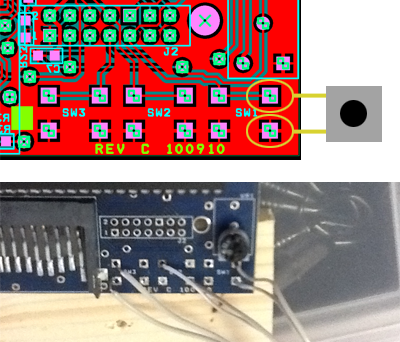
Wires connections for microswitches
Each microswitch has 4 pins but I connected only 2 pins cause the other 2 are redundant. Regarding to the orientation on the picture above, I connected a top pin of each button with a top node on the board and a bottom pin of each button with a bottom hole on the board.

Drilling two holes for the screws

Connecting the microswitches to the emulator board

Attaching the screws into the case

Fixing the perfboard with the screw nuts
3. Mounting the HxC inside the Amiga
I will install the HxC emulator in the position of the old floppy drive. I’ll try to leverage the floppy drive screw holes. I need to put the emulator board at the right height in order to allow the insertion of the SD card from the floppy disk slot. I’ll cut a little board of wood and use it as a platform for the HxC.

Preparing for wood cutting
")
The HxC connected to the wood board (note the washers I’m using to adjust the height)

Adjusting the height using the washers

The final result
4. Mounting the LCD Display into the case
Looking at the pictures above, you probably noticed a gray rectangle in my Amiga case. It’s what remains from my first attempt at mounting the emulator display. My first idea, in fact, was to put the LCD near the Commodore logo, as I saw in one of the pictures I found in the Lotharek’s website.

A picture of a mounted LCD from Lotharek’s website
Unfortunately, only after cutting the plastic cover with a hot kinfe and after hours spent smoothing the hole’s edges, I realized that there was absolutely no room for the LCD under that place.

First cut for LCD accomodation

My first idea was to put the buttons and the LCD here
After realizing that I cut the LCD hole in the wrong place, I tried to find some good way to fill it. I finally decided to use a plastic filler to fill it up.

Covering the hole

Preparing for the filler

Closing the back side

Filling up the hole

Smoothing

Final result
As you can see, the filler did a good job but the final result was a bit ugly. Thus I decided to create a tag to cover the gray zone. I designed a little tag with some instructions describing the hoverhanging buttons functionalities.

The tag and the buttons
Learning from the lesson of my previous mistake, this time I’m looking very carefully for another position where to put the LCD display. I finally found a place with enough room for the display near the upper left corner of the Amiga logo.

LCD Hole
And now I need a cable for connecting the LCD to the emulator board. I decided to use a PC IDE cable. The 40 pin female connector fits exactly in the board’s LCD male pins. The problem is in the connection with the LCD female inputs. I bought some needle connectors and soldered them to the LCD cable’s wires.

Elements for the LCD cable

Final result

The LCD cable is working
After testing the cable, I finally installed the display into the Amiga case.

Floppy emulator installation complete
Here’s a video of the HxC in action:
About the twisted cable : No need to cut it, just change the jumper setting on the HxC 😉
Thank you, I just updated the section about the twisted cable.
Hi!
Nice setup dude!
I am about to engage in a similar project myself, and have some questions for you.
Why didn’t the display fit? How did he do it on his website?
Even though you have some great photos, I’m a bit confused about the way you attached the buttons… Do you have more detailed photos or could you explain it better for stupid little me?
Cheers
Hi Troels, thanks for your comment.
The display didn’t fit cause it was too tick for the room under the case in that position. Maybe in the picture on lotharek’s website he was using a thinner one, not the version you can find on the HxC.
About the buttons: do you need info on the cable connections or the way I attached the perfboard to the Amiga case?
I’ve just discovered this blog and I think it looks great so far! I was thinking of buying one of these devices for my Amiga A500 Plus, but I wondered how to connect it because it seems to be compatible with other computers as well. I don’t want to get rid of my internal disk drive and this project seems too complicated for me at the moment, anyway. Isn’t there a way of connecting this device to the external floppy drive port, normally used as df1: ? I hope there is. If so, would you show me how to do that?
I think it is possible to connect a floppy emulator to the external port. If you search on google you can find some discussions about this topic. The main problem with the external amiga port is connecting all the pins. In fact the amiga external floppy port is a DB23F 23 pin connector while the HxC emulator has two connectors: one for power supply and the other for a 34pins internal floppy cable. You should look for schematics of each port and try to figure out how to connect them.
However, if you decide to go on with the external emulator, I think that the rev F of the lotharek HxC would be nice: http://lotharek.pl/product.php?pid=42
In that case, I don’t know how to do it. I’ll just have to make do with an external floppy drive. I have no idea why Lotharek doesn’t make a version of this which doesn’t just plug in to the external disk drive port. I’ve already got a floppy drive emulator called the SIO2SD which just plugs into the Atari 8 bit SIO port and it’s amazing!
I think the reason is that the HxC is conceived as a generic floppy emulator, not only for the Amiga. While the internal floppy drive connetion is pretty standard for every machine (the internal floppy cable, straight or twisted), the external connection (where existing) varies considerably over different systems. However you can try to ask Lotharek directly about this, maybe he can provide an easy solution.
I know, I’m a bit late, but just in case someone lands here on this blog and needs an answer to the question: Yes, you can use HXC as DF1 on the Amiga, you just have to set the jumpers accordingly. I have successfully used HXC as an external drive (mounted into the external drive case… 😀 ), so I know for sure it works fine. 😉
Great!
Hi,
Excelent blog 🙂
I too am attempting this project on my Amiga 500, could you please give me a little more info regarding the cable connections for the buttons. I think I have it figured out but just want to be sure before I unsolder them from the board.
I also opted for an Indivision ECS Scandoubler (http://amigakit.leamancomputing.com/catalog/product_info.php?products_id=918) to allow connection to any VGA monitor, works a treat and overcomes the 50Hz display modes.
Nice setup though 🙂
Hi. I created a picture to show you the correct connections for the buttons. As you can see below, each button has 4 pins but actually you need only 2 pins, the other 2 are redundant: regarding to the orientation on the picture below, just connect a top pin of the button with a top node on the board and a bottom pin of the button with a bottom hole in the board.
If you look carefully at the pictures in this article, you can notice that in the first picture where I show the first desoldered button, I made an error in the cable connections (i wrongly connected the 2 top nodes). The other pictures are correct.
Thanks Giuseppe, thats exactly what I needed 🙂
I am doing one of these right now !!
Nice! I hope my article will be useful.